My Last model is going to be a TIE Bomber. This is what looks like a double body TIE Fighter, so i could reuse some elements again so that I save some time. However, When I placed the blueprints onto the planes and alligned them, none of the previous elements matched up and so I felt that to make a good model, I would create it from scratch. The only elements that I reused are the exhaust and the front window parts. As the TIE Fighter's and the TIE Bomber's are still very similar and they have the same components (only just slightly different), I can still use similar techniques to create the model. Here are the blueprints that I used for my TIE Bomber;
To create the body of the cockpit (The left body on the front view blueprint), I used the
line tool to trace around the outside of the sideview body and then I used the
Lathe Tool to create the 3D object. The Lathe tool takes a 2D object and spins it round 360 degree's leaving a solid mass within the lines. This Lathe was done in the Y direction and left me with a perfect cylinder shape with nice groves and details. Here is the body without any of the components attatched;
Now I have the main shape, I just made some minor adjustments to the shape. I used
extrude on the back end of the cylinder so that I have a hole in the cylinder for the exhaust to fit inside. Also I done the same in the front so that there was some depth when the window is attatched. Here are the changes I make;
Now I add in the Exhaust and add the window. To give the window a better effect, I adjusted the position of the middle donut and the rectangles so that it had a spherical characteristic;
Here is the Cockpit Body completed;
Now I am going to create the body of the bomber (The Right body on the front view blueprint). This was done using the same technique as the cockpit, however I used a slightly different guideline so that the shape of the bomber was slightly different to the cockpit;
Again I created holes in the ends of the cylinder, However the extrude tool was making bad results as the polygons where all different shapes. This is a problem i noticed that can occur when you use the lathe tool. If the outline that you draw with the line tool isnt perfectly symetrical, The polygons on the inside are all different sizes and it makes operations such as extrude difficult to do. Therefore I decided to delete the central polygons as I wanted to have holes in the front and back and therefore I ddint mind the inside of the model being hollow. Here is the Bomber body after I deleted the polygons;
Now I will use the same exhaust as I did with the cockpit, However I needed to enlarge it slightly using the scale tool as the hole in the body is large than the exhaust.;
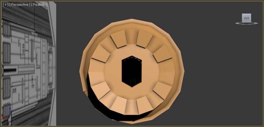
To create the front, I done exactly the same technique as I did to create the exhaust, I used the
inset tool on a cylinder and then it left small trapiez shapes. The only difference is that instead of inset and extruding the individual polygons around the outside inwards, I only
extruded a few of them outwards so that they stick out. I also used the
Boolean tool and subtracted a NGon
extruded shape from the cylinder so that there was a hexagonal hole in the front. Here it is;
Now add in some detail using the
line tool and
extruding shapes;
Now I need to create the Sensor that hangs off the bomber body. I drew round the outline of the sensor in the front view using the
line tool. I then
extruded the 2D shape to create the sensor. I then added some detail to the front of the sensor. I created a box and then split the front polygon into multiple polygons using the
slice plane tool. I then used a technique called
Hinge from edge. This enable me to create this effect on the detail;
So now thats the bomber body completed;
Now I decided to create the wings. Using exactly the same techniques as I did for the previous TIE fighters, I used the
NGon tool and
extruded and moved the vertices using the
move tool. I moved them to match both blueprints in both of the front and side views. I then used the
Mirror Tool to create both of the wings. Here is the progress so far;
Now all thats left to do is to join them up by making wing joints. I used the
line tool and
extruded it. I then added detail to the wing joints by making various shapes and also using the
boolean tool to cut a hole in the wing joint. Here is the wing joint with the detail inside.
Mirror the joint so that they joint the other wing to the bomber body;
Now all thats left to do is to join the two halfs with a middle joint. Again I used the
Line tool and
extruded the shape. I then used the slice plane tool to cut of some of the details. The top part of the middle joint has been
detatched and then scaled down slightly and place back on top of the middle joint. To create the other details, I drew round the detail on the blueprint and then I made it 3D by
Extruding it and once I had the shape, I used the
Slice plane tool so that I could adjust the hights of certain parts of the detail. Here is the detailed middle joint;
So now thats all of the elements of the TIE Bomber complete, Here the final product;


No comments:
Post a Comment