I am required to create a Story board to briefly show the main shots of the scene and to discribe what happens thoughout the scene. I have a picture of my story board below as I sketched my scene out on paper rather than using a computer. Here is the image of the Story Board;
As my drawing skills are not very impressive, Im going to explain the story board below;
The scene starts out with a close up of a TIE fighter. The camera then pans out to reveal a huge fleet of TIE fighters 'Marching' through space. The Pan out reveals multiple debris and destruction behind the TIE fighters as they proceed forwards. The camera stays panned out looking at the debris as the TIE fighters move out of the front of the shot. Suddenly there is a short overhead shot of an Imperial Ship, then a close up towards Darth Vaders ship, showing that the two ships have noticed eachother. Then a perspective look to the left of Darth Vaders TIE fighter followed by another perspective look to the right of him, emphasising the two TIE Bombers either side. Then the orders are given and the camera goes behind the TIE fighters as they unleash their weapons upon the helpless fleeing imperial ship.
Friday, 14 October 2011
Thursday, 13 October 2011
Materials and Maps
This week we are looking at materials and how we can adjust material properties to create effects such as metal and wood. We have also looked at the different types of Maps that can be used to make a material and assign it to an object.
The first excercise was to create a material that looked like a shiny metal. To do this we have to adjust the specular highlights of the material. For the Shiny metal, I used the following specular Highlights;
As you can see, in the first material selection, the sphere is shiny and has a metal like characteristic. Here it is on an object;
Now I need to create a material that looks like wood;
And here it is on an object;
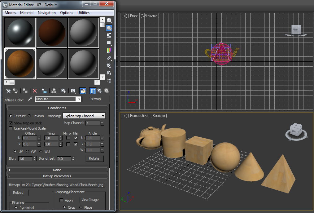
The second excercise was to apply a bitmap image onto an object. For this excercise, there was a bitmap named that we was require to use, but when I attempted the excercise, the image did not exist so i used a wood style material instead.
I needed to apply this bitmap to a variety of primitives in order to see how the bitmap was mapped to the object;
3DS Max managed to put the bitmap image on most of the object wuite effectively. However there are a few issues with certains shapes. For example, on the pyramid shape, the bitmap image doesnt meet up properly along the verticle edges.
These are errors that we would need to be aware of when creating models and adding materials to them.
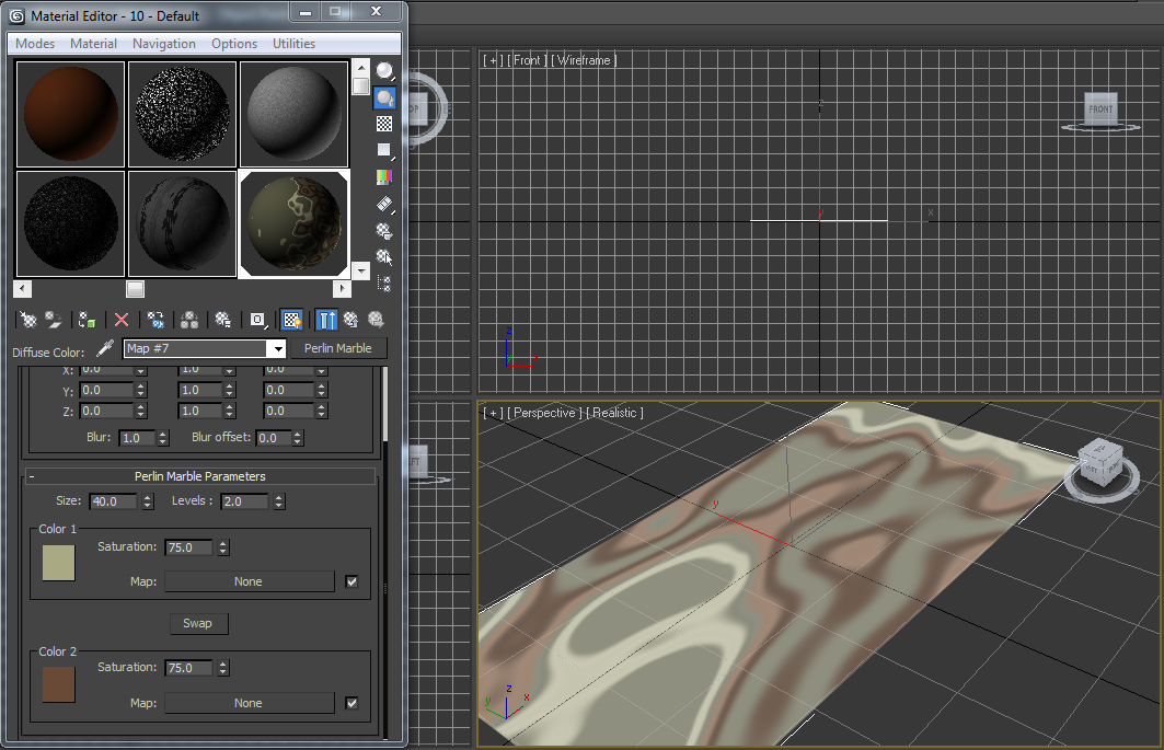
The final excersise was to look at Procedural Maps. These are diffent kinds of maps that can me used on an object to give them different effects. Below are all the different Procedural Maps on a Plane;
Cellular;
Dent;
Marble;
Noise;
Perlin Marble;
Smoke;
Splat;
Waves;
The first excercise was to create a material that looked like a shiny metal. To do this we have to adjust the specular highlights of the material. For the Shiny metal, I used the following specular Highlights;
As you can see, in the first material selection, the sphere is shiny and has a metal like characteristic. Here it is on an object;
Now I need to create a material that looks like wood;
And here it is on an object;
The second excercise was to apply a bitmap image onto an object. For this excercise, there was a bitmap named that we was require to use, but when I attempted the excercise, the image did not exist so i used a wood style material instead.
I needed to apply this bitmap to a variety of primitives in order to see how the bitmap was mapped to the object;
3DS Max managed to put the bitmap image on most of the object wuite effectively. However there are a few issues with certains shapes. For example, on the pyramid shape, the bitmap image doesnt meet up properly along the verticle edges.
These are errors that we would need to be aware of when creating models and adding materials to them.
The final excersise was to look at Procedural Maps. These are diffent kinds of maps that can me used on an object to give them different effects. Below are all the different Procedural Maps on a Plane;
Cellular;
Dent;
Marble;
Noise;
Perlin Marble;
Smoke;
Splat;
Waves;
Tuesday, 27 September 2011
Boolean Operations and Grouping Objects
This week we looked at some techniques to joing complex shapes together and how to use a shape to cut out from another shape. We also looked at grouping shapes and the ways in which grouping shapes can be useful. We took a look at using the allign tool to allign shapes accurately.
The technique used to cut shapes within shapes and to join shapes together is called Boolean.
To do the excercise I first alligned a box and a sphere so that they are intersecting together in the following way:
The Boolean operation can be found within the Create tab, in Geometry and using Compound Objects. Heres the menu Below:
Before we select Boolean however, we need to make sure that the object we want to be 'cut out of' is selected, so I have selected the box. Now that Boolean option is selected, click on the 'Pick Operand B'. This means to click on the object that you want to be the 'Cutter'.
Thats what happens when we Subtract A from B and have the 'Copy' option selected. This keeps the cutter as an object.
Below are the other ways in which the Boolean tool can be used:
Move and Subtract A-B;
Move and Subtraction B-A;
Move and Intersection;
The technique used to cut shapes within shapes and to join shapes together is called Boolean.
To do the excercise I first alligned a box and a sphere so that they are intersecting together in the following way:
The Boolean operation can be found within the Create tab, in Geometry and using Compound Objects. Heres the menu Below:
Before we select Boolean however, we need to make sure that the object we want to be 'cut out of' is selected, so I have selected the box. Now that Boolean option is selected, click on the 'Pick Operand B'. This means to click on the object that you want to be the 'Cutter'.
Thats what happens when we Subtract A from B and have the 'Copy' option selected. This keeps the cutter as an object.
Below are the other ways in which the Boolean tool can be used:
Move and Subtract A-B;
Move and Subtraction B-A;
Move and Intersection;
Move and Union;
Cut and Remove Inside;
Cut and Remove Outside;
So those are all the different things that you can do with the Boolean tool. These operations will prove to be effective when creating my Models.
We also looked at grouping and the grouping excercise was set to help us to understand the way in which 3DS Max groups objects.
First of all i started with 4 shapes, Box, Sphere, Cone and Tube. I then needed to group together the Box and the Tube and then the Cone and the Sphere;
Now I needed to group together the two groups and call them All Shapes;
Now to show that the group all shapes still remembers that it is made up of 4 shapes, but 2 groups, I need to ungroup to see how they are named;
If I Explode the group, instead of ungrouping, it will ungroup at all levels and leave all the objects as single object;
Wednesday, 21 September 2011
Introduction to Modelling and Basic Techniques
This is the first week for 3D modelling and animation. We are using the program 3ds Max from Autodesk to create three dimensional models and to create animations. We was briefed on the assignment, which stated that we would be required to create a short animated clip, of no longer than 30 seconds, that is to be based on a scene from either one of the star wars films, animated series or books.
First of all we looked at the interface of 3ds Max and looked at some basic techniques. We looked at the viewports and the different views in which you can use. We also have been introduced to using basic primitives such as Cubes, Cylinders and Spheres.
The first excercise is to create a boat steering wheel. Here is my first attempt at creating a model in 3ds Max;
To create the verticle poles, I used the Cylinder tool and rotated them around to form the 'star' shape. To create the centre circle, I used the donut tool to create a 2D primitive. I then edited it and used extrude to bring the shape up and create a 3D shape. I then rotated it by 90 degrees to be alligned with the verticle poles.
The second Excercise was to create a house. To do this I created a cube and added the poly sections to create a good template for the windows and door to be taken out of it. Once I created the cube I then converted it into a Editable Poly by right clicking on the primitive, Convert to > Editable Poly. This now will allow me to edit the primitive by adapting the polygons, vertices, edges, boarder and elements. Once I selected the polygon where I wanted to put a window/door space, I selected Extrude and then extruded the face inside of the house.


Thats the base done, now I need to create the roof. To create the roof, I created a Pyramid and set the height, width and depth to the required size;
Lower the Roof onto the base to complete the house;
The final excercise is to create a castle. This will use a range of primitives and also will require various editing effects and techniques to create the castle.
Here is the castle:
Firstly, I created the walls by making some lines then extruding them upwards to create 3D walls.
To create the four towers on each corner of the castle, I made a cylinder and then edited the top two polygons to bring it outwards then to point back in at the top.
To create the moat around the castle, I created a plane and then selected a row of polygons around the created walls and moved the polygons downwards. This then adjusts the polygons attatched to the moved polygons to create slopes for the moat.
Lastly, to create the drawbridge, I created it by making a plane and then I rotated it slightly to make it slightly angled and to give it a bridge like characteristic.
First of all we looked at the interface of 3ds Max and looked at some basic techniques. We looked at the viewports and the different views in which you can use. We also have been introduced to using basic primitives such as Cubes, Cylinders and Spheres.
The first excercise is to create a boat steering wheel. Here is my first attempt at creating a model in 3ds Max;
To create the verticle poles, I used the Cylinder tool and rotated them around to form the 'star' shape. To create the centre circle, I used the donut tool to create a 2D primitive. I then edited it and used extrude to bring the shape up and create a 3D shape. I then rotated it by 90 degrees to be alligned with the verticle poles.
The second Excercise was to create a house. To do this I created a cube and added the poly sections to create a good template for the windows and door to be taken out of it. Once I created the cube I then converted it into a Editable Poly by right clicking on the primitive, Convert to > Editable Poly. This now will allow me to edit the primitive by adapting the polygons, vertices, edges, boarder and elements. Once I selected the polygon where I wanted to put a window/door space, I selected Extrude and then extruded the face inside of the house.
Thats the base done, now I need to create the roof. To create the roof, I created a Pyramid and set the height, width and depth to the required size;
Lower the Roof onto the base to complete the house;
The final excercise is to create a castle. This will use a range of primitives and also will require various editing effects and techniques to create the castle.
Here is the castle:
Firstly, I created the walls by making some lines then extruding them upwards to create 3D walls.
To create the four towers on each corner of the castle, I made a cylinder and then edited the top two polygons to bring it outwards then to point back in at the top.
To create the moat around the castle, I created a plane and then selected a row of polygons around the created walls and moved the polygons downwards. This then adjusts the polygons attatched to the moved polygons to create slopes for the moat.
Lastly, to create the drawbridge, I created it by making a plane and then I rotated it slightly to make it slightly angled and to give it a bridge like characteristic.
Subscribe to:
Posts (Atom)